Hardware Description
Pinout and Description
The connector pin assignment is as follows. All I/O pins function at max 10mA and 3.3V rating.
Connector J1 Pinout

| PIN | PIN No. | DESCRIPTION |
|---|---|---|
| RSTn | p6 | monoZ:Jet Reset pin |
| TX (UART, transmit) | p7 | Host <-> monoZ:Jet comm. UART, baud rate:115200 |
| RX (UART, receive) | p8 | Host <-> monoZ:Jet comm. UART, baud rate:115200 |
| - | p9 | Reserved GPIO |
| GND | p10 | Ground connection |
Connector J2 Pinout

| PIN | PIN No. | DESCRIPTION |
| VBUS | p1 | 5V DC input power supply |
| GND | p2 | Ground connection |
| INT (MOD2HOST_INT) | p3 | monoZ:Jet to host inttrupt pin |
| WKP (HOST2MOD_WKP) | p4 | monoZ:Jet wake up pin |
| GND | p5 | Ground connection |
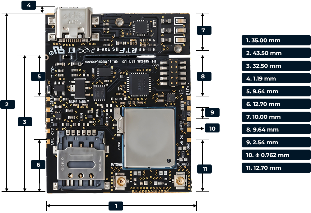
Mechanical Specifications
The mechanical dimensions of monoZ:Jet is provided in figure 6. A standard tolerance of ±0.05mm shall apply for all dimensions.
